 Download
The Most Complete Pipe Umbrella System Construction Procedure
Time:2024-06-07From:sinorock View:
Introduction
Tunnel construction in unstable terrains poses significant challenges, particularly when dealing with fractured or weathered rock masses. In such scenarios, the advanced large pipe umbrella system emerges as an optimal solution to stabilize and support the tunnel structure. This article will delve into the intricacies of constructing a pipe umbrella system, highlighting the skills required, the technological processes involved, and best practices to ensure structural integrity and safety.

Skills Requirement
Environmental and Pre-Construction Considerations
To avoid complications during construction, it is imperative to avoid earthwork excavation during the rainy season. Prior to excavation, robust drainage systems such as intercepting ditches and gutters should be established to manage water flow and prevent soil erosion. Proper planning and construction of these drainage systems are essential to maintain a stable working environment and protect the structural integrity of the tunnel entrance.
Excavation Techniques
Excavation of the cut-and-cover section should be executed meticulously, layer by layer, from top to bottom. Each layer of excavation should be accompanied by shotcrete application for side and slope protection. This process not only stabilizes the slopes but also minimizes the risk of landslides and cave-ins. Upon reaching the height of the excavation contour line of the vault in the undercut section, excavation should proceed vertically to the bottom of the designated upper half section, followed by temporary concrete spraying to seal the tunnel face.
The Technological Process of Pipe Umbrella Support System
Large Diameter Pipe Umbrella
1. Hole Formation and Drilling Sequence: To ensure the stability of the hole formation and prevent the collapse of adjacent holes, drilling should be performed in an alternating sequence. Initially, odd-numbered holes are drilled, followed by even-numbered holes. The holes, with a diameter of 140mm, allow for the smooth installation of φ108×6mm steel pipes.
2. Drilling Angle and Pipe Specifications: When using long pipe sheds (φ108×6mm), the drilling angle should be maintained between 1° to 3°, with a circumferential spacing of 40cm. Each pipe length should be 40m, segmented into 9m sections connected by an 89cm casing. To facilitate jacking, each section should overlap by 3m, and small holes of 10mm diameter should be drilled at 15cm intervals on the steel pipe.
3. Drill Pipe Coupling and Straightening: The coupler for the drill pipe must match the material of the drill pipe, with internal threads and a wall thickness of at least 10mm to ensure sufficient strength, rigidity, and toughness. During drilling, a straightener should be used to maintain the alignment of the drill pipe, preventing deviations due to thrust and vibration forces.
4. Precision in Drilling: Accurate control of the drilling rig's vertical axis is crucial. Hole positions and numbers should be marked on the poured sleeve arch, distinguishing between odd and even holes. Odd holes use seamless steel pipes, while even holes use perforated (plum blossom) steel pipes. Immediate installation of steel pipes and injection of cement slurry are necessary to prevent hole collapse and verify the grouting quality.
5. Drilling Techniques: The boom of the trolley should be firmly pressed against the face to minimize vibration and enhance drilling accuracy. Initial drilling should be slow, increasing to normal speed after penetrating 20cm. The first section of the drill pipe should be driven into the rock formation, stopping 20-30cm from the tail to allow for manual coupling and further drilling.

Construction of Long Roof Pipe
1. Pipe Jacking Process: The construction process begins with drilling a guide hole larger than the outer diameter of the steel pipe. Utilizing the impact and thrust of the drilling rig, the shed pipe is jacked along the guide hole without generating torque.
2. Production of Pipe Fittings: The pipe shed comprises Φ108 seamless steel pipes in 3m and 6m sections. The joints of adjacent pipes should be staggered to avoid stress concentration. The initial even-numbered section is 3m, and the first odd-numbered section is 6m, followed by 6m sections. The buried length of the pipe shed is 24m, with alloy steel sheet-type hollow drill bits welded to the front section to prevent deformation.
3. Installation and Alignment: After drilling and clearing the hole, steel pipes are installed. Deflections during drilling are measured and corrected promptly to meet design specifications. Proper alignment during pipe jacking is maintained by the boom of the trolley.
4. Takeover and Jointing: When the first steel pipe is nearly fully jacked into the hole, the rock drill reverses to detach the coupling sleeve. The process repeats for subsequent sections, ensuring alignment and secure connections using manual chain pliers.
5. Sealing and Reinforcement: The ends of the steel pipes are sealed using burlap and annular wedge rings, which are then welded to the pipe shed. To enhance rigidity, residual materials within the pipes are drilled out for reinforcement.

Preparation of Slurry
1. Mixing Cement Slurry: Cement slurry is mixed in a high-speed mixer following strict construction ratios. Cement water glass slurry is injected into the steel pipe with initial and final pressures of 0.5~1MPa and 2.0Mpa, respectively. Post-grouting, the seamless steel pipe is filled with 1:1 cement mortar to enhance strength and stiffness.
2. Feeding Sequence and Admixtures: Water is combined with retarders and admixtures in specific proportions before adding cement. The mixture is stirred for 2-3 minutes to ensure homogeneity.
3. Quality Control: The weight of external admixtures should be 5%-10% of the cement's weight, with retarders comprising 2%-3%. It is essential to prevent contaminants like cement blocks or paper sheets from entering the slurry.
4. Construction Records: Detailed records of the grout preparation and grouting process are maintained to analyze and ensure the effectiveness of the grouting.
5. Slurry Storage: The prepared slurry is stored in tanks with low-speed agitators to prevent precipitation and segregation, maintaining the slurry's consistency for optimal use.
Grouting
1. Grouting Procedure: After installing the perforated steel flower tube and placing it in the steel cage, M20 cement slurry is injected using a grouting machine. The initial pressure is 0.5~1.0MPa, reaching a final pressure of 2MPa. Grouting is maintained for 15 minutes to meet design requirements.
2. Grouting Sequence and Techniques: The grouting follows principles such as "both sides first, then the middle" and "jump-hole grouting," progressing from lower to higher slurry concentrations. This method ensures the comprehensive filling of rock masses around the borehole, enhancing structural integrity.
3. Grouting Long Tube Sheds: Grouting for long tube sheds aims to consolidate the surrounding soil and rock, ensuring the slurry diffusion radius is no less than 0.5m. Segmental grouting is employed to control the process and meet design specifications.
Self-Drilling Rock Bolt
Introduction to Self-Drilling Rock Bolts
In addition to the pipe umbrella system, the self-drilling rock bolt presents a more accessible and efficient solution for tunnel support, particularly in complex geological conditions. The self-drilling rock bolt system integrates drilling, grouting, and anchoring into a single process, offering significant advantages in terms of safety, efficiency, and convenience.
Components of self-drilling rock bolt
The self-drilling anchor bolt system comprises several key components:
- Hollow Anchor Bar: Facilitates grout flow and enhances bonding with the surrounding rock mass.
- Coupler: Connects multiple anchor bars to achieve the desired length.
- Nut: Secures the anchor bar in place.
- Drill Bit: Penetrates the rock formation and enables drilling.
- Plate: Distributes load and provides surface support.
- Centralizer: Ensures the anchor bar remains centered in the drilled hole.
Construction Process
Conclusion
The advanced pipe umbrella system and self-drilling rock bolt are both essential techniques in modern tunnel construction, particularly in unstable geological conditions. The pipe umbrella system offers robust support for fractured or weathered rock masses, while the self-drilling rock bolt provides a versatile and efficient alternative for various ground conditions. By understanding and implementing these construction procedures, engineers and construction professionals can ensure the stability and safety of tunnel projects, overcoming the challenges posed by complex and unstable terrains.
latest news
-
- 3 Crucial Factors That Impact the Quality of Self-Drilling Hollow Bolts
- Time:2025-01-26From:This Site
- As we all know, the quality of the self-drilling hollow bolts is vital to the whole project. It determines if the project is safe for the people in future use. Then, what will affect the quality of the self-drilling hollow bolts?
- View details
-

- Self-Drilling Anchor Bolt Construction in Complex Geological Slope
- Time:2025-01-24From:This Site
- During construction, Self-drilling hollow anchor bolt integrates drilling, grouting and anchoring functions, which significantly improves drilling efficiency. And under the action of pressure pump, the grouting in the rock strata and voids is full, which ensures the grouting thickness and anchoring effect.
- View details
-
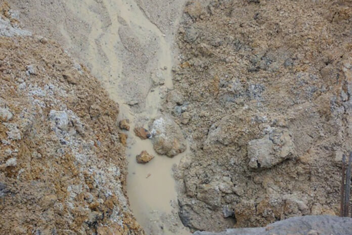
- How Does Self-drilling Rock Bolt Drill in Quicksand Geological Condition?
- Time:2025-01-19From:This Site
- This in-depth guide explores how self-drilling rock bolts function in quicksand geological conditions, covering the challenges, construction methods, and best practices for ensuring effective anchorage in unstable, fluidic soil layers.
- View details
-
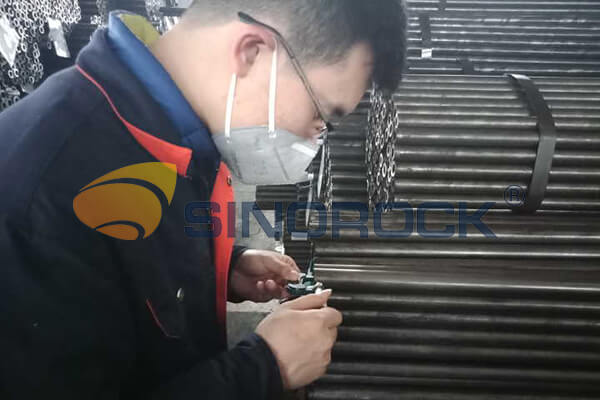
- Quality Control: the Vital Factor of A SDA Bolt Factory
- Time:2025-01-09From:This Site
- Sinorock’s comprehensive quality control system, from supplier management to outgoing inspections, ensuring the highest standards for self-drilling anchor bolts in construction.
- View details
-
.png)
- International Women's Day with Strawberry-picking
- Time:2024-03-09From:This Site
- Marked the annual observance of International Women's Day, and to commemorate this significant event, Sinorock organized a special strawberry-picking event exclusively for its female employees.
- View details
-

- Celebrate the 74th anniversary of the founding of the People's Republic of China
- Time:2023-10-01From:This Site
- On October 1st every year, we observe the annual National Day, commemorating the birth of our beloved motherland.
- View details
-
.jpg)
- SINOROCK to Attend EXPOMINA PERÚ 2024 in Lima, Peru
- Time:2024-08-10From:This Site
- Sinorock to Attend EXPOMINA PERÚ 2024 in Lima, Peru
- View details
-
.jpg)
- SINOROCK to Participate in MINING AND METALS CENTRAL ASIA 2024
- Time:2024-08-08From:This Site
- SINOROCK to Participate in MINING AND METALS CENTRAL ASIA 2024
- View details
-
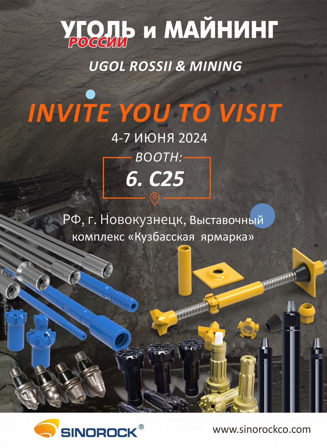
- SINOROCK Gears Up for UGOL ROSSII & MINING 2024 with Custom Mining Solutions
- Time:2024-05-15From:This Site
- SINOROCK is thrilled to announce its participation in the highly anticipated 32nd International Trade Fair for Mining Technology, UGOL ROSSII & MINING 2024. The event will take place at the Exhibition complex "Kuzbass Fair" in Novokuznetsk, Kemerovo region - Kuzbass, Russia, from June 4th to 7th, 2024.
- View details
